May 8, 2026
How to Use Mold Flow Analysis for Large Components

Overview
- Mold flow analysis helps manufacturers predict flow behavior, optimize gate placement, and improve cooling before production begins.
- This process reduces defects such as warpage, sink marks, and uneven shrinkage while minimizing trial-and-error adjustments.
- Richfields supports large-component projects with advanced simulation capabilities and proven injection molding expertise to deliver consistent, high-quality results.
Large plastic components are especially vulnerable to defects when flow behavior, gate placement, and cooling are not evaluated before tooling begins. For companies in the US, these oversights translate directly into production delays, rework costs, and missed timelines.
That vulnerability is precisely why mold flow analysis has become an essential step in large-component manufacturing. It gives manufacturers a way to predict and resolve these issues before a single mold is cut.
This article explains how to use mold flow analysis for large components, walking you through each stage from simulation setup through defect prediction and final design refinement.

This preliminary setup allows mold designers and tooling teams to evaluate how molten plastic will behave before the mold is manufactured. Setting the correct geometry, mesh structure, and material data helps ensure the simulation reflects accurate molding conditions.
The geometry of a component forms the foundation of any mold flow analysis. The mesh acts as a framework that allows the simulation to calculate how molten plastic will travel through the mold.
Too coarse a mesh may overlook critical details, while too dense a mesh can slow down the simulation unnecessarily. For large automotive components such as bumpers with curved surfaces and mounting brackets, a well-calibrated mesh is essential to accurately simulate how plastic fills and cools across the entire part.
Material properties such as viscosity, shrinkage, and thermal conductivity influence flow patterns, potential warpage, and cycle times. Proper material selection at this stage helps your team optimize mold design.
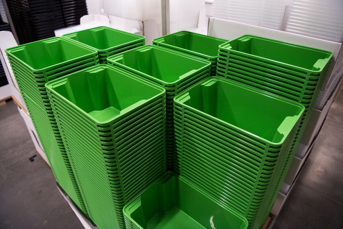
For example, when designing a large storage bin, you can choose a polypropylene grade with known shrinkage and flow characteristics. This selection helps the simulation predict how the part will fill the mold, where sink marks may form, and where to position the cooling channels.
Proper gate placement ensures that the material fills the cavity efficiently. It also reduces the risk of defects such as air traps and weld lines, and helps minimize cycle time. Analyzing different gate configurations helps achieve a balanced flow throughout the component and determines whether multiple gates are needed for complex or large parts.
Using multiple gate locations is an effective strategy for large or complex components. Shorter flow paths help distribute molten plastic more evenly across the cavity.
This approach lowers injection pressures and minimizes the risk of incomplete filling or short shots. On the bumpers or dashboards of large automotive vehicles, placing two or more gates ensures the material is distributed uniformly across the entire area.
Achieving a balanced flow ensures that molten plastic fills the mold evenly and consistently, which is critical for high-quality parts. Mold flow analysis can visualize the melt front during the fill phase. This allows adjustments to gates, runners, or geometry so that all areas of the cavity fill almost simultaneously—typically within 0.5 to 1.0 seconds.
Evaluating pressure and cooling performance helps ensure the entire molding cycle, covering filling, packing, cooling, and potential warpage, is optimized before the mold is manufactured. This analysis can reveal issues such as incomplete filling, excessive clamp tonnage requirements, or dimensional instability.
Mold flow simulation calculates the peak injection pressure required to push molten plastic through the runners, gates, and cavity during the filling stage. This ensures the required pressure remains within the injection molding machine’s operating limits.
If the required pressure is too high, it may indicate flow-path restrictions or areas requiring design adjustments. For example, thick-to-thin transitions or long flow paths in large components can increase resistance and require higher injection pressure.
Cooling performance strongly influences cycle time and part stability in injection molding. Cooling channels are typically positioned about 1.5–3 times the part’s wall thickness from the cavity surface. Straight channels are often used for simple molds, while conformal channels are better suited for complex shapes like bumpers.
Uneven cooling can cause uneven shrinkage, which may twist or distort long parts. Mold flow analysis helps balance cooling by analyzing coolant flow, inlet temperature, and channel spacing to maintain even mold temperatures
This final stage helps evaluate factors such as part geometry, wall thickness, and cooling performance. It allows manufacturers to predict issues like warpage, sink marks, or uneven shrinkage before production begins. This further enables final design adjustments to meet quality and dimensional requirements while reducing costly trial-and-error during actual molding.
Warpage occurs when different areas of a part shrink unevenly during cooling, leading to twists, bends, or other distortions. Mold flow analysis visualizes deformed shapes with deformation plots, so it’s easier to quantify issues such as twist or bow in long parts.
Running a full mold flow analysis covering cooling and warping after the fill, pack, and cool phases helps predict shrinkage. It also identifies distortions caused by residual stresses, uneven cooling, or fiber orientation in large components.
Uniform wall thickness ensures even flow and consistent cooling, reducing defects such as sink marks or short shots. Mold flow analysis reveals thick sections that cool slowly and thin areas prone to incomplete filling.
For large parts such as bumpers, a target thickness of 2 to 4 mm helps maintain quality. Simulation results guide CAD adjustments, including coring bosses, adding gussets, or tapering transitions, and confirm balanced filling with minimal sink marks.
Understanding how to use mold flow analysis for large components can save time, reduce defects, and improve production efficiency.
Richfields is a China-based injection molding manufacturer specializing in large-component production, combining advanced mold flow simulation with proven tooling expertise to support OEM and product development programs. Contact us today to discuss how we can help optimize your next large-component project.

Prevent defects in large injection molded parts by controlling cooling, material flow, tooling design, and process conditions from the start.
Read more
Partnering with a single injection molding provider streamlines operations by centralizing oversight of design, prototyping, production, and quality checks, slashing administrative burdens and miscommunications.
Read more
A reliable molding partner improves productivity and sustainability by reducing downtime, minimizing waste, improving quality, and stabilizing supply chains.
Read more
Optimize large customized molding projects by stabilizing processes, maintaining tooling, managing resin quality, and improving production efficiency
Read more